
Software Center

User Manual download
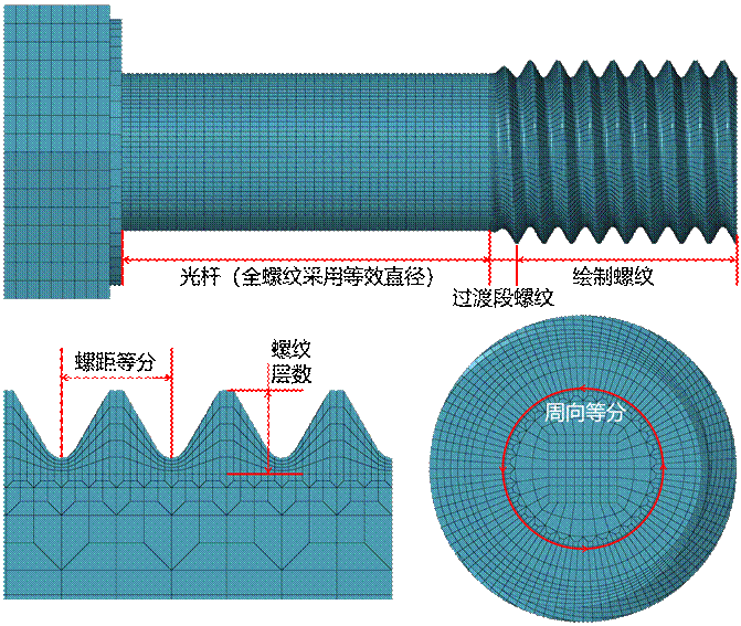
- Bolt Parameters Area
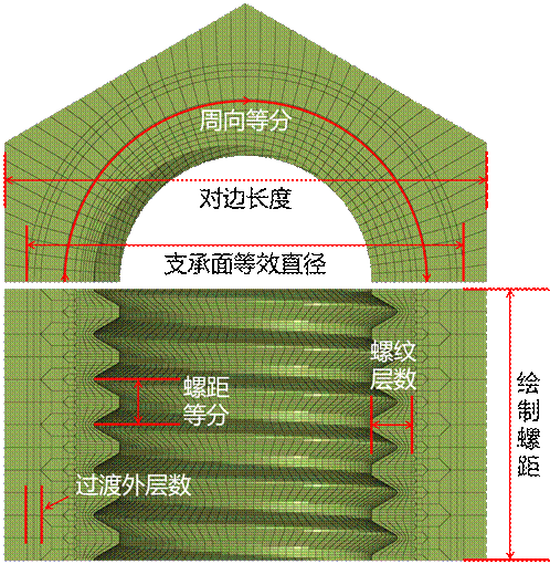
- Nut Parameters Area
- Bolt Head Parameter Area
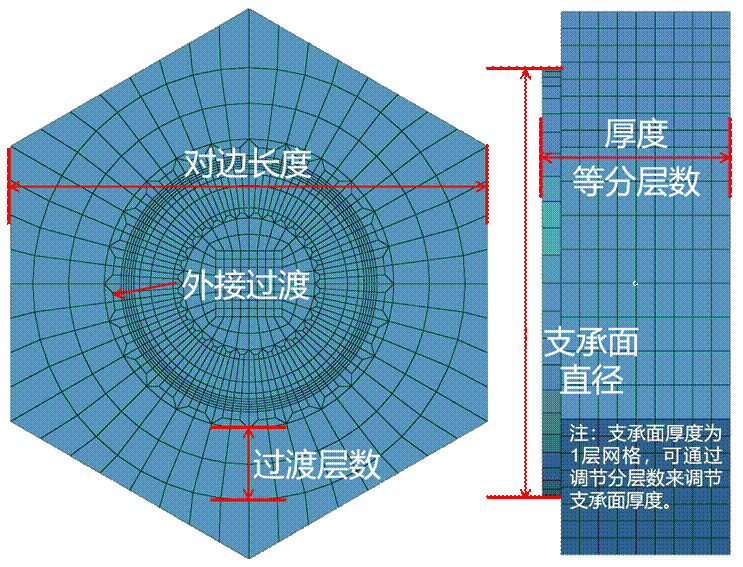
The above diagram can be popped up by clicking on the blank area of the corresponding component in the design interface.
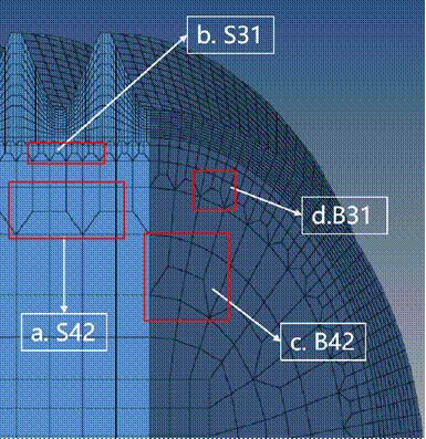
There are four transition methods available in the transition parameter selection area:
S42: Section 4 to 2. S represents section, 42 represents the transition method from dense to sparse mesh as 4 mesh to 2 mesh.
S31: Section 3 to 1. S represents section, 31 represents the transition method from dense to sparse mesh as 3 mesh to 1 mesh.
B42: Bottom section 4 to 2. B represents bottom, 42 represents the transition method from dense to sparse mesh as 4 mesh to 2 mesh.
B31: Bottom section 3 to 1. B represents bottom, 31 represents the transition method from dense to sparse mesh as 3 mesh to 1 mesh.
S = Pitch Equivalent Number;
B = Circumferential Equivalent Number;
Transition Layer Impact:
In the S direction: S42(1) will cause S/2 (S42 is the transition method when S is being finished, requiring S/4), S31(2) will cause S/3.
Two conditions must be satisfied in the B direction:
① B42(3) will make B/2, B31 will make B/3, and B layer needs to be divided into 4 parts finally (transitioning to the center square), and the number 4 is definitely divisible.
② When transitioning outward, the B layer needs to be divided by the nut transition method, then divided by 6 (the bolt head needs to be divided into 6 parts).
It must be ensured that the number of elements is divisible by all transition layersFor accurate computation, the number of layers for the nut is generally the same as that for the bolt.
Using the transition layer [S42 S42 B42 S42 B31] as an example:
Pitch Layer Number S:
S/2/2/4(S42 requires division by 4 when rounding down)=integer;
Circumferential Layer Number B:
(Both conditions must be satisfied)
① B/2/3/4 (B layer needs to be divided into 4 equal parts, this 4 is necessarily divisible)=integer
②B/(Nut Transitional Method)/6 (Bolt head requires 6 divisions)=integer
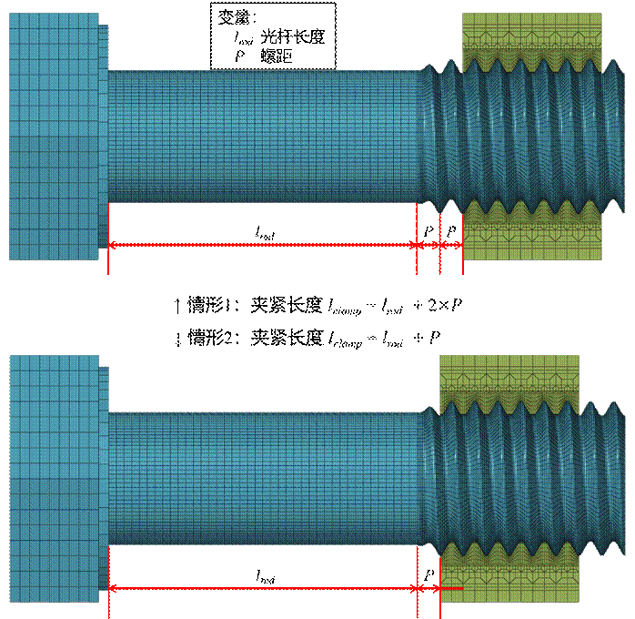
Generally, when a bolt clamps the connected members, there are two scenarios:
Case 1 - In addition to the reserved retraction slot, reserve one thread pitch (this case is applicable for finite element simulation using rotational tightening loading methods, such as the rotation angle method, torque method, etc.)
Case 2 - Only reserved retraction slot, no separate reservation of pitch (this case is applicable for finite element simulation using non-rotational tightening loading methods, such as the Bolt Load loading method).
The specific calculation formulas for the two cases are shown in the figure below.
The finite element model generated by this software has duplicate nodes, and the "merge duplicate nodes" operation must be performed in the finite element to be used perfectly.
This section uses Hypermesh 2020 and Abaqus 6.14 as examples to demonstrate the "merge nodes" operation.
Hypermesh 2020 software operation:
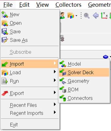
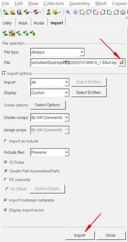
First, open the Hypermesh software, click the 'File' menu, then select 'Import' -> 'Solver Deck' option. In the Import tab, choose the file path to import, then click 'Import' to import the finite element model.
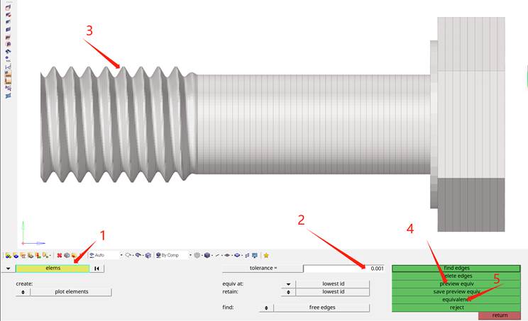
In the lower options interface, click 'Tool' -> 'edges' to enter the next operation interface.

Change the selection range to 'elems', set tolerance to 0.001, hold down Shift and left-click to select the entire part with the mouse, click 'preview equiv' to highlight the repeated nodes, then click 'equivalence' to merge nodes.
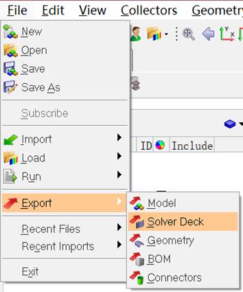
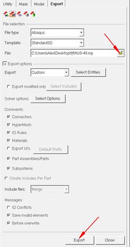
After completing the node merging operation, click on the 'File' menu -> 'Export' -> 'Solver Deck' option. In the Export tab, select the file path to be exported, and click 'Export' to export the finite element model. If you need to export the model in other finite element software (such as ANSYS), select the corresponding software in the 'File type' option.
Abaqus 6.14 software operation:
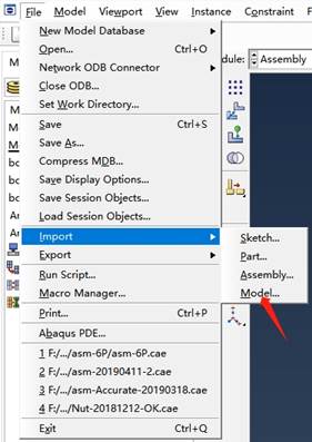
First, open the Abaqus software, click the 'File' -> 'Import' -> 'Model' option in the menu bar, and select and import the INP file.
Switch the Abaqus module to the 'Mesh' interface, switch the object from 'Assembly' to 'Part', and click the 'Edit mesh' button to enter the editing interface.
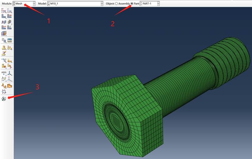
In the editing interface, click 'Node' in the directory to switch the tab, select the parts to be merged, and then click the 'Merge' button. A 'Merge Tolerance' will pop up at the bottom of the software. Set the tolerance to '1e-04', and press the 'Enter' key on the keyboard.
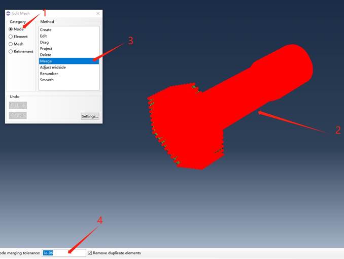
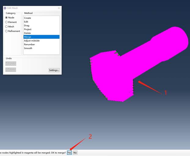
At this time, the nodes to be merged will be displayed in purple, and the software will prompt whether to merge the nodes. Clicking 'Yes' will complete the node merging operation.
The precise finite element mesh for bolts uses a fully eight-node hexahedral element. Its greatest advantage is that it can perfectly reproduce the complex contour of bolts while ensuring high mesh quality, making finite element calculations more likely to converge.
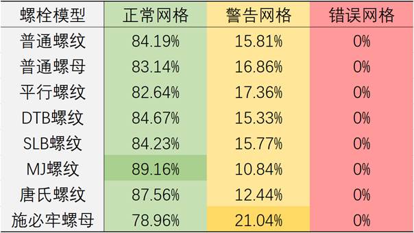
The table shows various mesh ratios for mesh elements of 55μm (high mesh density). The proportion of high-quality meshes is almost entirely above 80%, and the proportion of error meshes is 0%. Note that this result is only for high mesh density data. If the density is reduced, the proportion of high-quality meshes will be higher.


 popular software