

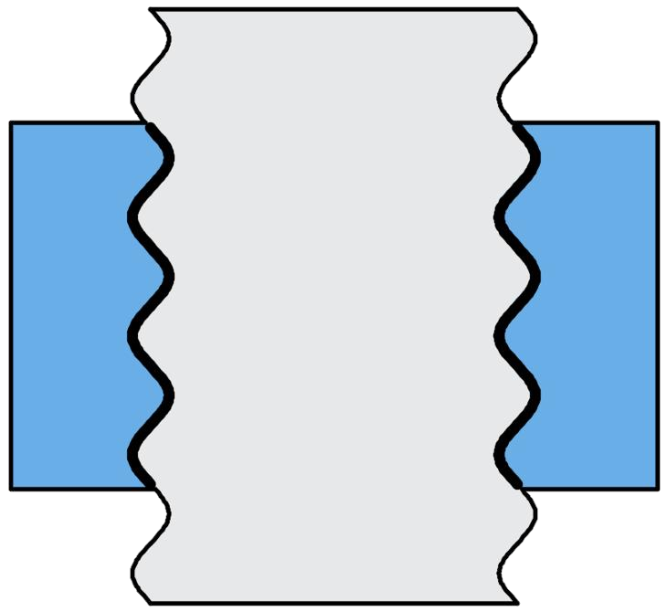


Thread Designer 3.1
From parameter definition,
to thread mesh.
Select the thread profile, enter geometric dimensions and mesh partition parameters. Thread Designer 3.1 converts clear parameter definitions into a mesh for threaded joints, exports the INP file, and connects your finite element analysis workflow.
Windows 7 / 8 / 10 / 11 · Download after logging in
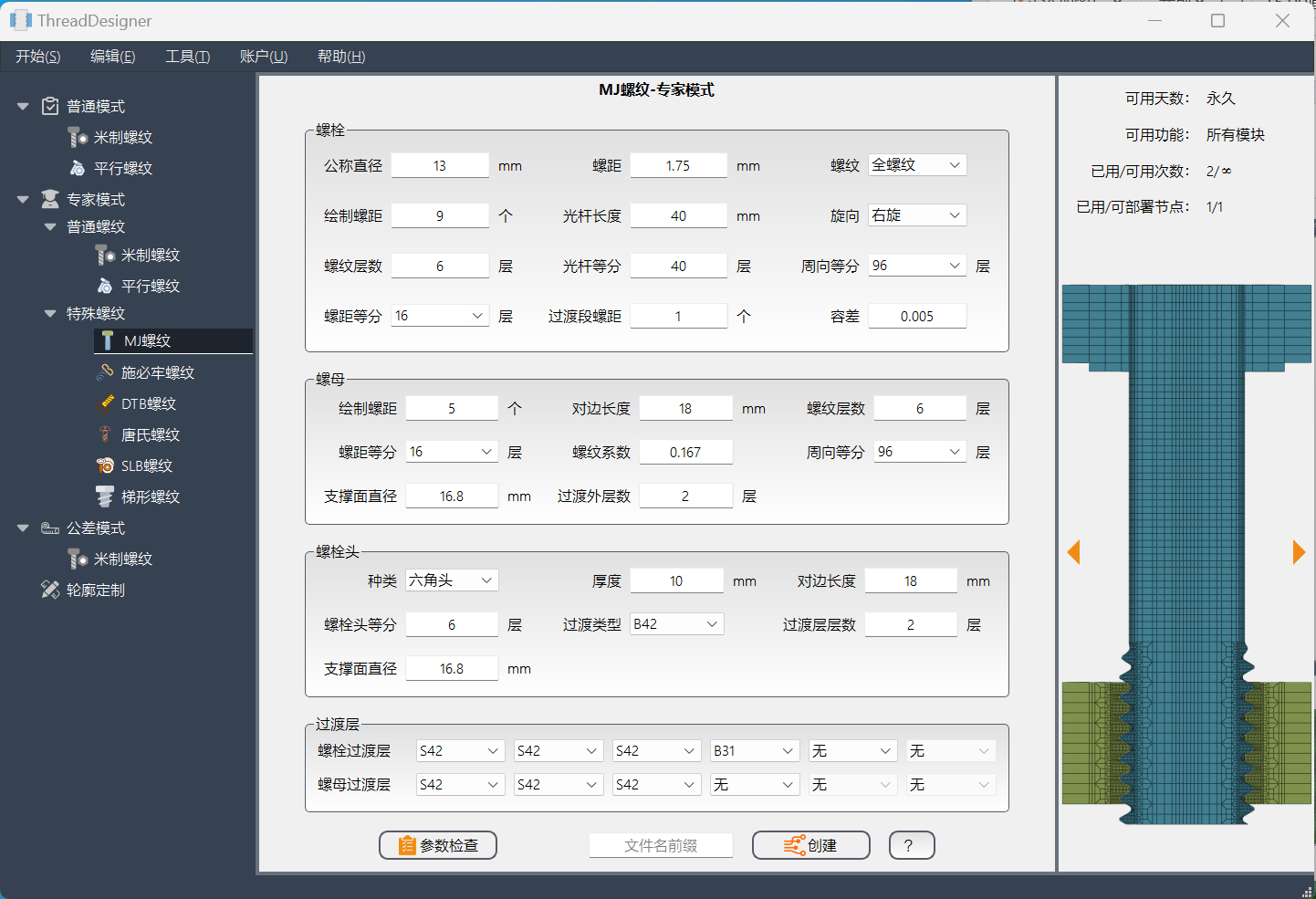
Bring engineering intent,
Written into every parameter.
From thread profile to size, from partition to transition.
The working method of 3.1 revolves around clear parameter definitions.
- thread profile is determined first
- Enter the corresponding parameter table from the type list. Metric, MJ, special threads, and custom profiles are authorized for use.
- Dimensions Defined
- Nominal diameter, pitch, shank length, along with nut and head dimensions, should be entered and verified separately.
- mesh is controllable
- Radial layer count, pitch division, circumferential division, and transition layer collectively define the discrete method.
- output has a destination
- Generate INP model, continue to configure material, contact, load, and analysis step in the finite element software.
different thread profiles
Retain individual geometric features.
These are examples of the mesh from the original desktop software.
Specific available types and validity period can be viewed in the personal center.
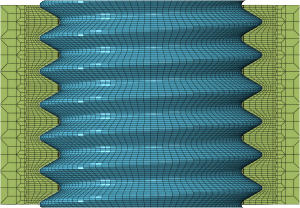
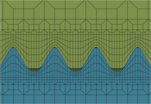
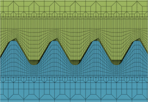
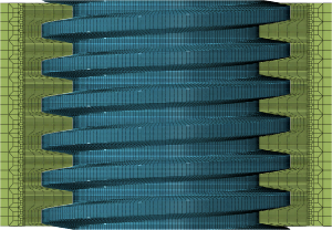
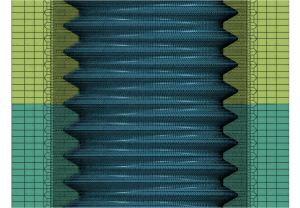
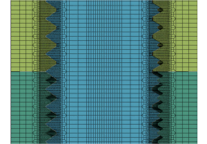
Desktop software includes metric, parallel, MJ, SAE, DTB, Tangshi, SLB, and trapezoidal types; the function range is limited by your desktop software license.
Parameter Definitions Completed
Deliver a mesh model that is ready for use.
3.1 Focuses on finite element modeling of threaded joints. After mesh generation, output the INP file, which is then handled by subsequent analysis software for material, boundary conditions, and solution settings.
- model output
- INP finite element model.
- usage environment
- Windows Desktop Software
- help and instructions
- Read the operation manual
- account and authorization
- Enter the Unified User Center
Choose a working style that suits you.
Thread Designer 3.1Parameter definition and thread mesh output. Currently available as a Windows desktop version.
Thread Designer 3.2 ↗Edit dimensions directly on the model, enhancing the connection organization and mesh inspection experience. Desktop version under development.TD Forge ↗The next generation of TD3, targeting precise modeling, connection analysis, and engineering research.Download and use
How to download and start using?
After logging into the Thread Designer account, click the Windows Download button to obtain the software. Installation and parameter instructions should be read from the operation manual; the desktop version supports online login and offline activation.
Can all thread types be used after logging in?
The thread types, term, frequency, and deployment nodes of the desktop software are managed according to account authorization. After logging in, you can view specific permissions on the 'TD3 Desktop Version' page in the unified personal center.
Are licenses for the desktop version and web version compatible?
Shared account, authorized separately. The number of 3.2 Web generations is calculated independently and does not overlap or inherit the authorization of 3.1 desktop software.
Would you like to model directly in the browser?
can be selected Thread Designer 3.2 WebOnline definition of M / MJ threads and multi-member clamped members, generate mesh and download the model, no installation required.
Thread details
Enter your engineering model.
Download the desktop version, or read the operation manual to understand the modeling process.