
Software Center

User Manual download
finite element simulationFinite Element Simulation (FEA) is an engineering analysis technology used to study and predict the behavior of physical systems through numerical simulation and calculation. It is based on the finite element method, which divides complex actual physical systems into many small elements (finite elements), and then analyzes these elements using mathematical methods. These elements can represent various structures, materials, and physical phenomena, such as solids, liquids, gases, heat, electricity, and magnetism. By performing numerical calculations on the interactions between these elements and boundary conditions, finite element simulation can simulate the behavior and performance of actual systems.
Finite element simulation is typically used in engineering, science, and design fields to solve various problems, such as structural analysis, heat transfer, fluid flow, and electromagnetic field analysis. It helps engineers and scientists evaluate different design solutions on computers, optimize product performance, reduce the need for prototype manufacturing and testing, lower development costs, improve reliability, and reduce potential risks. This technology has broad applications in modern engineering and scientific research.
Finite element simulation methods are widely applied in the design and verification of bolted joint structures. The engineering value of finite element simulation for bolted joint structures lies inIt allows engineers to evaluate connection performance through numerical simulation, reducing the cost of actual testing, improving design reliability, optimizing bolt size, material, and structure, lowering manufacturing costs, ensuring the safety and durability of connections, promoting the efficiency and quality of engineering projects, and significantly reducing major engineering accidents caused by insufficient connection structure performance.
Finite element simulation has high requirements for the mesh. A good finite element mesh should meet and have the following characteristics:
1) The element shape is simple and the element characteristic equation is easy to solve;
2) The mesh model should be as accurate as possible to the original domain;
3) Use the fewest elements that meet the required accuracy to keep the solve efficient.
However, due to the complex contour of the bolt, its difficulty in finite element modeling is much higher than that of general mechanical structures. Therefore, in simulation analysis, the bolt must be simplified. With the development of modeling and simulation technology, the finite element analysis model for threaded components has undergone multiple evolutions in the past few decades:
1) Bolt model using beam elements: Use beam elements to simulate bolts. The model is simple, the contact definition is simple, and convergence is easy, making it suitable for many situations. Beam element simulation for boltsCannot simulate the tightening process of threaded fasteners and the rotational loosening behavior under external loads。
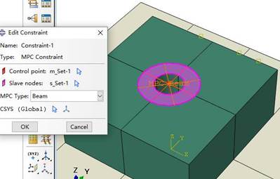
2) Model of a cylindrical body without threads: The bolt and nut are modeled as 'character' shaped solids, with a simple structure, making modeling and meshing convenient and efficient. The cylindrical body model without threads is alsoUnable to simulate tightening process and loosening behavior。
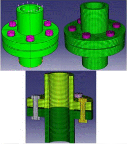
3) Axisymmetric mesh model (2D). Use this for stress concentration at the thread root and axial load distribution in the bolt, butIt cannot simulate the tightening process and loosening behavior, nor can it display the contact behavior of the thread engagement surface.。
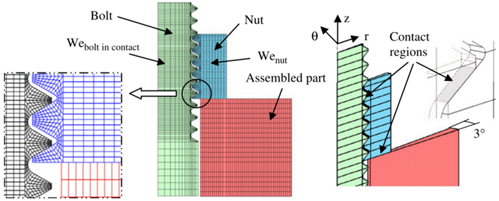
4) Axisymmetric mesh model (3D). A 3D bolt and nut model with zero helix angle can readily be meshed with regular hexahedral elements. This finite element model can be used to evaluate nonrotational loosening in bolted joints. However,This model has no helix angle, no helix line, it is actually multiple parallel thread forms, not real threads.
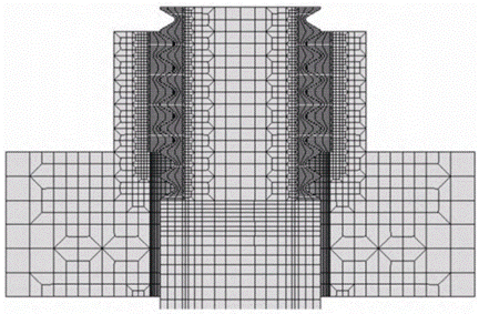
5) Tetrahedral mesh model: The tetrahedral mesh model for threaded components can be automatically generated in finite element software, but it is difficult to control the mesh density in different regions. The number of elements is large, and the computational load is significant. Using a tetrahedral mesh to divide the threaded component model, it is difficult to ensure the quality of the mesh at the thread root and the accuracy of the thread profile. Most importantly, the tetrahedral mesh model willThere are difficulties in convergence, and the calculation accuracy is not high。
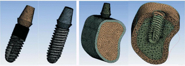
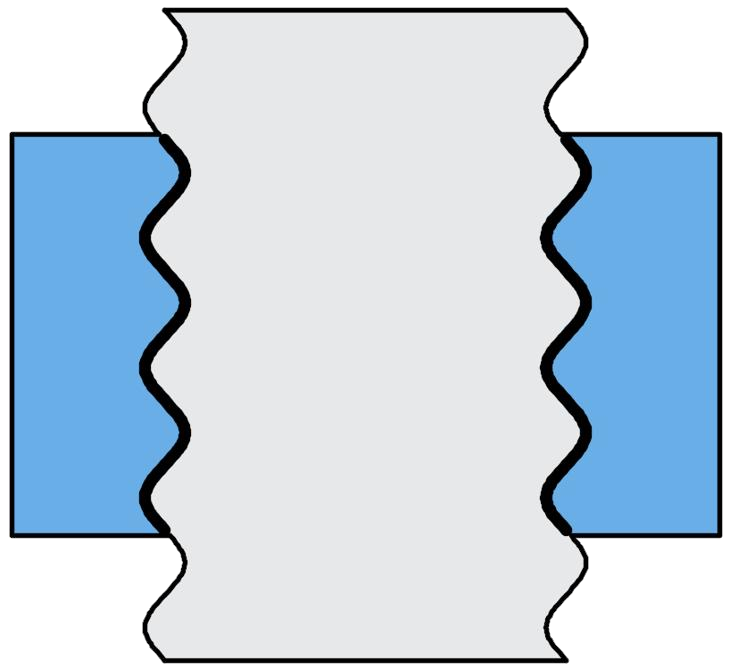
6) Tied model (thread teeth tied to the body). Sweep a 2D thread-tooth mesh along the helix. Mesh the teeth and the body separately and join them with a tie constraint. However, because the model ties the two parts together,Nodes at the interface cannot transmit forces and displacements effectively;。
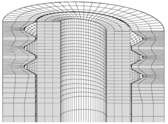
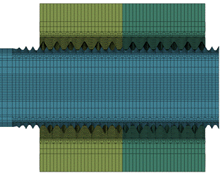
7) Parametric Precise Modeling Method: The core of this method is to analyze the geometry of the thread to obtain a segmented function of the thread profile, resulting in a finite element model of the threaded component with precise geometry and high-quality hexahedral mesh.This model matches the actual thread profile height and can accurately simulate the tightening process of threaded parts, the evolution of contact state on the thread engagement surface, and the loosening behavior of bolts. It is the most effective finite element model for studying the failure mechanisms and design verification of threaded joint structures.
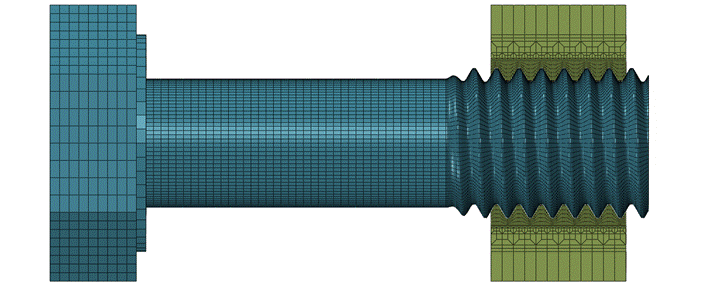
M10Precise finite element mesh for bolts.
beam element | cylinder | 2D axially symmetric | 3D axially symmetric | tetrahedral | Thread and Body Binding | Parametric Accurate Finite Element | |
Simulate tightening process | × | × | × | × | √ | √ | √ |
Simulate loosening behavior | × | × | × | × | √ | √ | √ |
Stress concentration in threads | × | × | √ | √ | √ | × | √ |
Thread contact state | × | × | × | √ | √ | √ | √ |
Is it easy to converge | √ | √ | √ | √ | × | √ | √ |
Data extraction difficulty | √ | √ | √ | √ | × | √ | √ |
VDI 2230 Part IIThe bolted joint finite element model is divided into four levels: the first-level model only models the components without considering the bolt itself; the second-level model treats the bolt as a line element, i.e., as a tensile member, beam element, or spring element; the third-level model models the bolt as an equivalent solid model, i.e., a bolt finite element model without considering the thread; the fourth-level model is the highest level, representing detailed modeling of the bolt, which needs to include the thread and all contact conditions in the contact surfaces, and precisely represent the details of the bolt.Thread DesignerThe model generated by the software fully complies with the fourth-level requirements of the VDI2230 standard.
VDI 2230 Part IIThe description of the fourth-level model is: the calculated stress of the fourth-level FEM conforms to the nominal stress definition required by the design concept in VDI 2230, and can be used to determine the nominal load. Furthermore, the local load of each position of the thread can be determined and evaluated through the corresponding local verification concept. Additionally, the minimum length of thread engagement also needs to be obtained through the fourth-level model, taking into account the elastic-plastic material properties. The evaluation of the precise finite element model of the bolt in VDI 2230 Part II can be summarized as follows:A more accurate method for bolted joint design and verification that can replace VDI 2230.
The Engineering Application Advantages of Precise Bolt Finite Element Model Are:
1) It is possible to simulate the tightening process, study the impact of tightening methods, tightening tools, and bolt parameters on the tightening process, and efficiently and cost-effectively obtain the optimal tightening strategy.
2) Simulate loosening behavior to facilitate research on bolt loosening mechanisms and anti-loosening measures.
3) Calculate the stress concentration of the threads, quickly determine whether static strength and fatigue strength are up to standard, reduce engineering risks.
4) Auxiliary or alternative to VDI 2230 standards for bolted joint design and verification.
Therefore, using a finite element model of threaded components with a profile matching the actual height to simulate the failure behavior of threaded joints is an effective means of proposing targeted anti-loosening measures and improving reliability. This method has been validated and accepted by the academic community over the past 15 years. However,The parametric precise modeling method for thread models still belongs to the frontier technology in the field of fastened joints. Thread mesh cannot be manually divided and requires computer programs to achieve this.Academic research on this topic is still concentrated in a few universities and research institutions in China, such as Southwest Jiaotong University, Xi'an Jiaotong University, Beijing Institute of Technology, Dalian University of Technology, etc.Each institution's algorithm is strictly confidential, and is in the stage of technical monopoly, forming multiple 'technological islands'.This also leads to academic research results being unable to be put into practice for a long time, and the practical advanced technology that should be widely applied in engineering has been only found in top-tier journal papers for many years.
Horycon (Tianjin) Technology Co., Ltd. works to advance fastened-joint engineering in China. The company worked with the research team led by Professor Minhao Zhu, a Changjiang Scholar and chief professor at Southwest Jiaotong University. More than a decade of research refined the theory of high-fidelity parametric finite element modeling for threaded components and led to a modeling tool for a range of bolt types.Thread DesignerAmong them, a significant portion of the precise models of special threads are internationally first, and have not been published in open literature.
The core value of the Thread Designer thread component finite element modeling software lies in,It assists technicians in quickly generating precise finite element meshes automatically, enabling engineering technicians with finite element calculation knowledge to rapidly achieve precise finite element simulation analysis of bolted joint structures. It enables research on bolt tightening, loosening, fatigue, and fracture behaviors, significantly reducing the technical barriers of bolted joint simulation.Applying academic frontier research results to practical engineering fields, bringing users a leap in capability, enterprises a quality improvement, the industry a technological advancement, and the country a scientific and technological development.
1.2.1 Software Overview
Balance high quality, high accuracy, and high efficiency, parametrically generate high-precision finite element models for threaded components, significantly improving the computational efficiency of numerical analysis for threaded connections. At the same time, it helps engineers with finite element analysis backgrounds to design and verify threaded connections, improving the efficiency of fastened joint design, reducing design costs, and enhancing structural safety and reliability.
1.2.2 Software Positioning
A finite element mesh generation tool (finite element preprocessor) to assist simulation personnel in completing accurate finite element simulation analysis for various threaded joint structures;
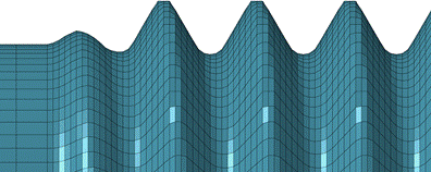
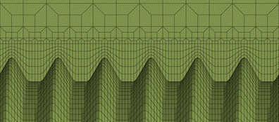
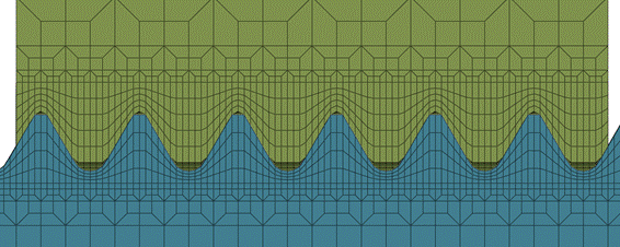
MJDetail of a high-fidelity aerospace thread finite element model
1.2.3 software features
Ultra-high degrees of freedom - can generate precise thread profile mesh of any type, size, transition, and arrangement.
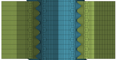
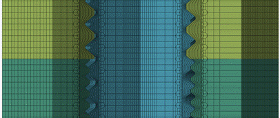
Metric Threads double start thread
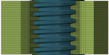
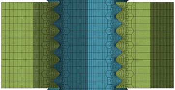
Trapezoidal thread Parallel thread
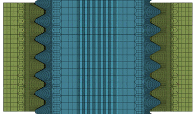
Sibolock nut Dun's thread
Various precise bolt finite element meshes


 popular software