
Software Center

User Manual download
This section describes the user interface, including explanations of each component. Note that due to software version updates, the interface displayed in this section may differ from your version, but the main functional logic remains consistent and does not affect understanding and use.
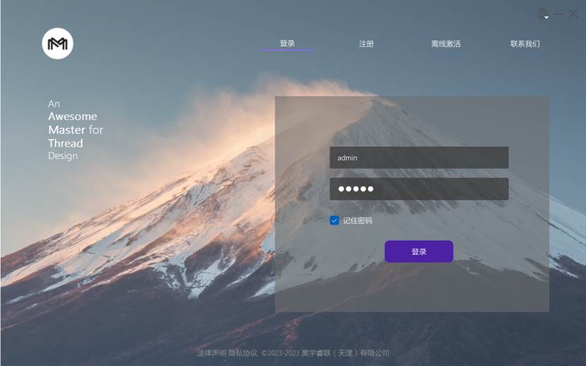
- The login interface includes four tabs: 'Login', 'Register', 'Offline Activation', and 'Contact Us'.
The 'Settings' button is provided in the upper right corner, allowing users to change the software language and other settings.
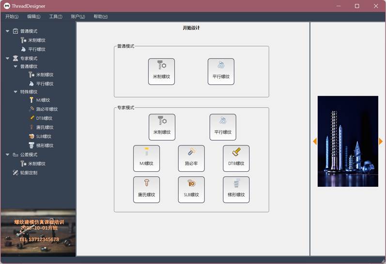
- The main interface consists of multiple components.
- The top menu bar includes "Start," "Edit," "Tools," "Account," and "Help" menus, providing different functional options.
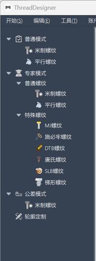
On the left is a model selection tree, which lists different thread types.
Right side includes a mode selection interface for selecting different working modes.
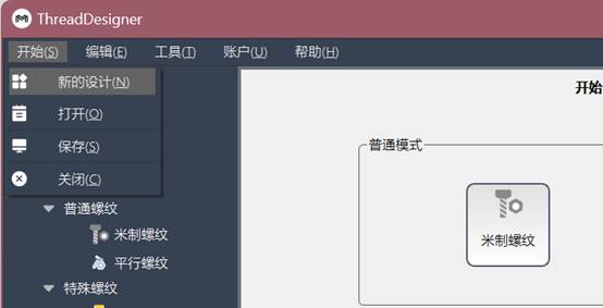
Start menu includes options: new design, open, save, close.
- The Edit menu provides options to clear and reset, as well as to set parameters to default values (the option is not available in the software version shown in the image).
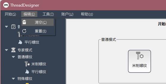
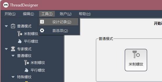
- The tools menu includes design records and preferences.
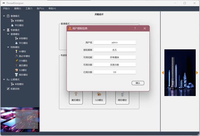
- Account Menu for Checking User Account Permissions
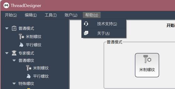
- The help menu provides technical support and information about the software.
In ordinary mode, displays 'metric threads' and 'parallel threads'.
- In expert mode, 'ordinary threads' and 'special threads' (including MJ threads, Wedge-locking threads, DTB threads, Tonneau threads, SLB threads, and trapezoidal threads) are displayed.
- Tolerance Mode and Contour Customization Functions Are Currently Unavailable
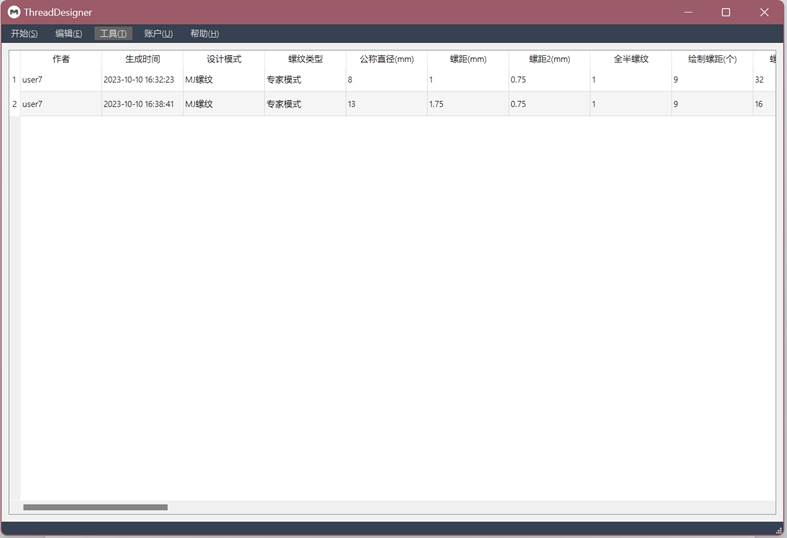
Records are saved for each model creation, allowing users to view historical designs at any time.
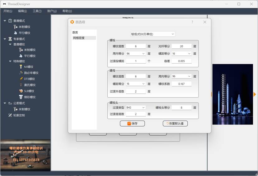
Preferences include language and mesh density options.
- Mesh density options allow users to adjust configuration parameters for different mesh densities, applicable to regular mode.
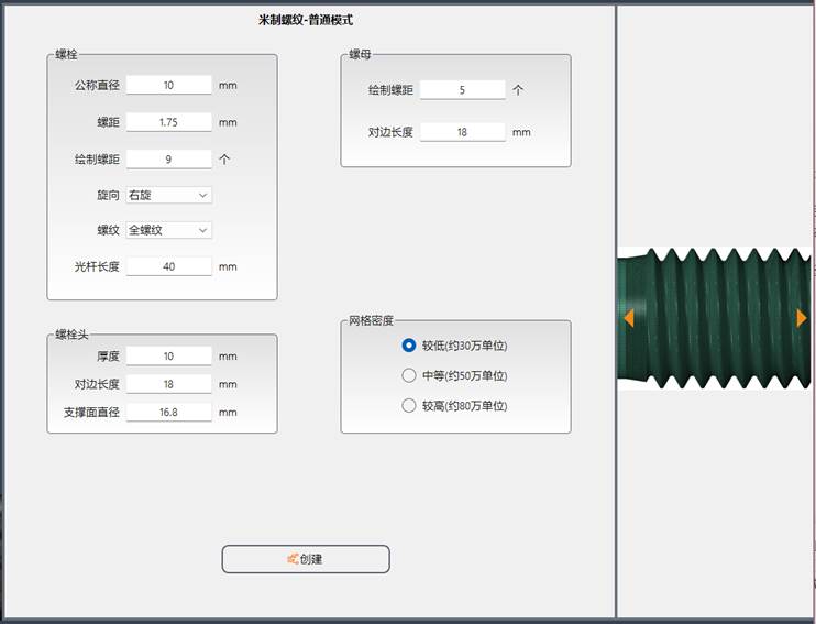
- The design interface is divided into the following areas:
- Bolt Parameters Area
- Nut Parameters Area
- Bolt Head Parameter Area
- Mesh density selection area
- Create button
Right-side schematic switch, used for visualizing parameters and design concepts.
- The design interface is divided into the following areas:
- Bolt Parameters Area
- Nut Parameters Area
- Bolt Head Parameter Area
- Transition Parameters Area
- Parameter Check Button
- Create button
Right-side schematic switch, used for visualizing parameters and design concepts.
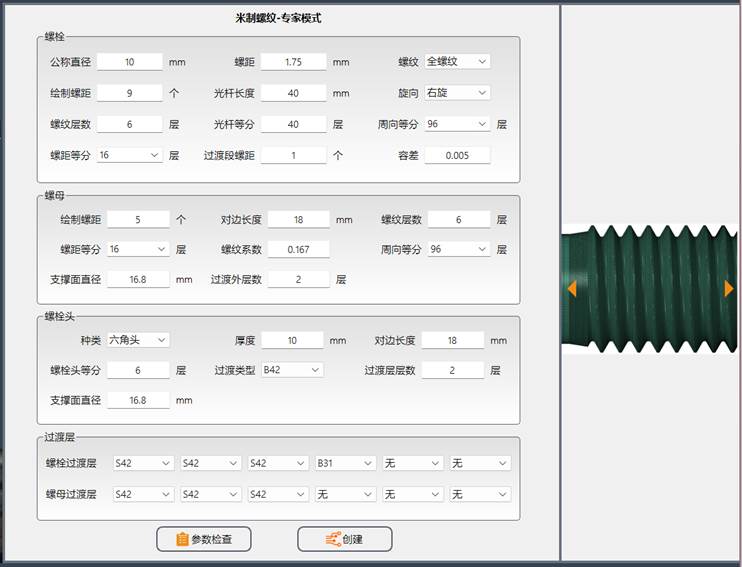
Users can click on any thread type to enter the design interface, then configure various parameters according to their needs, perform checks, and generate the corresponding precise finite element model file.
This section describes the user interface overview to help users become familiar with the various parts and functions of the software. It helps users operate and navigate within the software.


 popular software