
Software Center

User Manual download
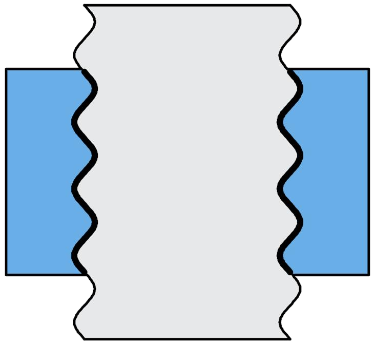
The right figure is used to display the appearance and structure of the selected thread type. It allows users to visualize the appearance of a bolt or nut before designing parameters. You can switch between different views by clicking the left and right arrows or by scrolling the mouse wheel over the image to better understand the model's appearance.
This issue is usually related to finite element calculations, possibly due to incorrect boundary conditions. The solution is as follows:
Check the boundary conditions of the model to ensure they are accurate and complete.
If the boundary conditions are correct, check for duplicate nodes that were left unmerged. Section 6 explains how to merge them.
First, you need to contact the software administrator or system administrator to express your request to add new modules or permissions.
When communicating with software administrators, clearly specify the specific content of the new module or permission you need. This includes the name of the module, its functions, and access permissions. Clear requirements will help administrators better meet your needs. The software administrator will provide a quotation and contract based on your requirements. Of course, users have the right to freely experience the new module content within a limited number of times.
After purchasing new modules, the software administrator will upgrade your account according to your needs. After the upgrade is complete, you can restart the software to ensure that the local function modules are open.


 popular software